Recent Projects
These are some JavaScript projects where JavaScript changes the value of the src (source) attribute of an image.
Click the links to test the Projects
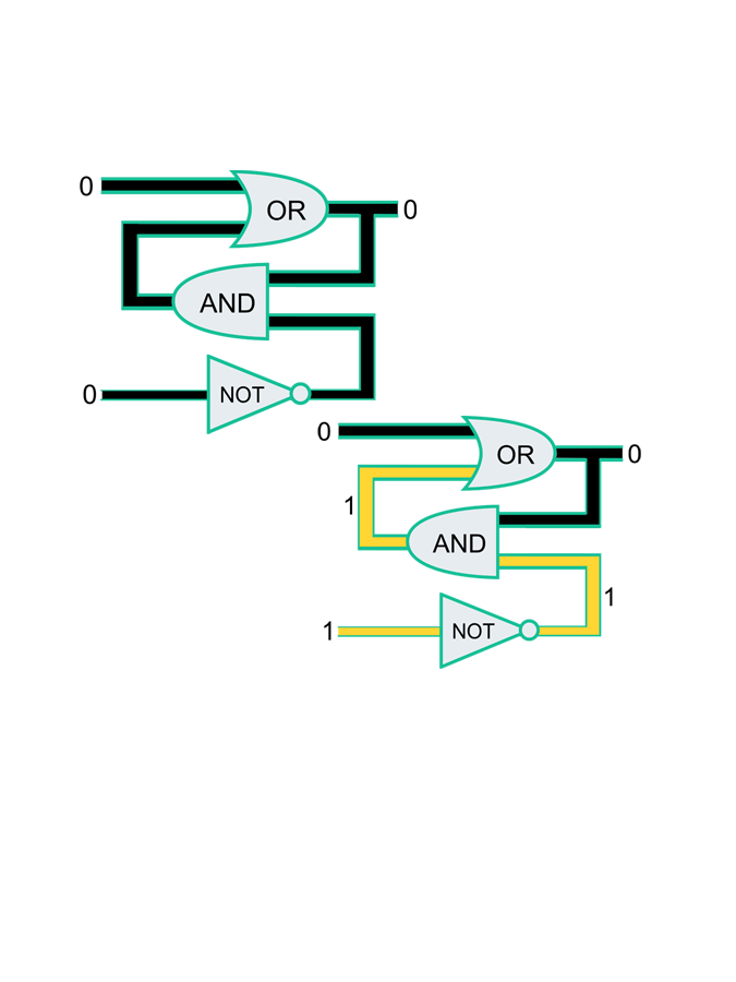
Logic gates are the basic building blocks of any digital system. It is an electronic circuit having one or more than one input and only one output. The relationship between the input and the output is based on a certain logic. Based on this, logic gates are named as AND gate, OR gate, NOT gate etc.
Project 1
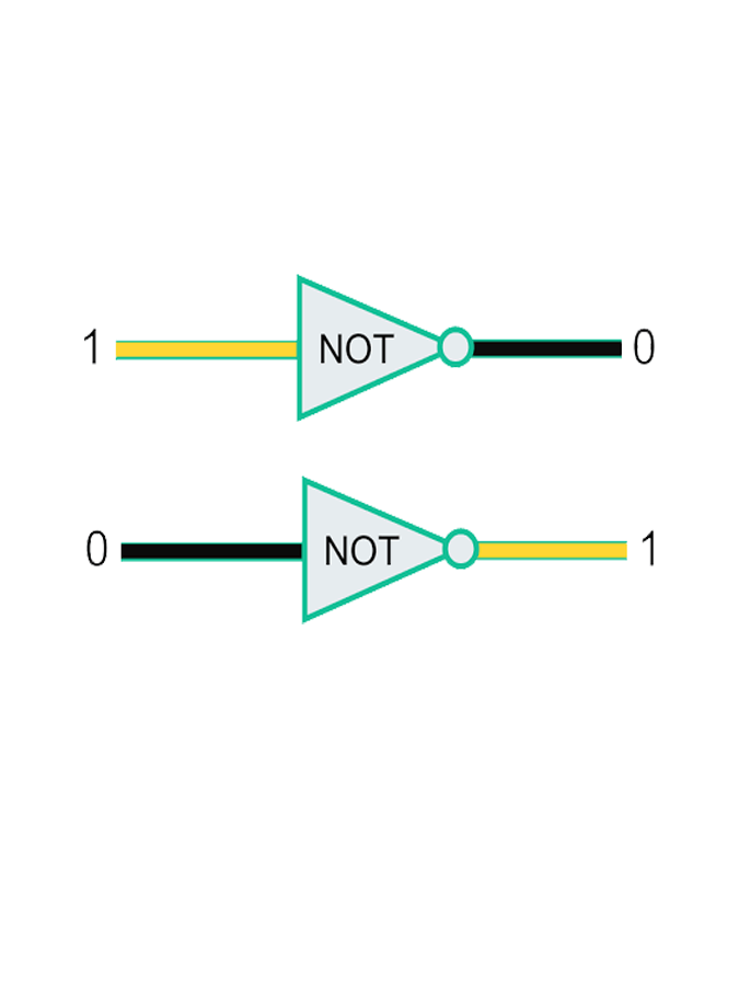
NOT Gate
NOT gate is a digital logic gate with one input and one output that operates an inverter operation of the input.The output of the NOT gate is the reverse of the input. When the input of the NOT gate is true then the output will be false and vice versa.
Click Here
Project 2
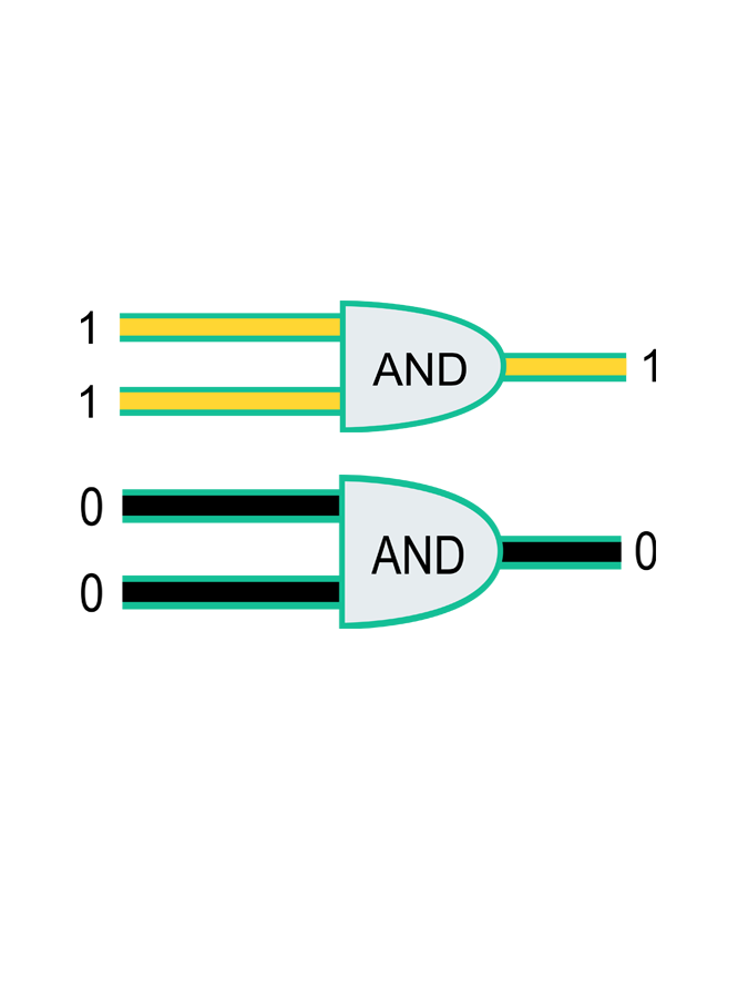
And Gate
AND gate is a digital logic gate with ‘n’ i/ps one o/p, which perform logical conjunction based on the combinations of its inputs.The output of this gate is true only when all the inputs are true. When one or more inputs of the AND gate’s i/ps are false, then only the output of the AND gate is false.
Click Here
Project 3
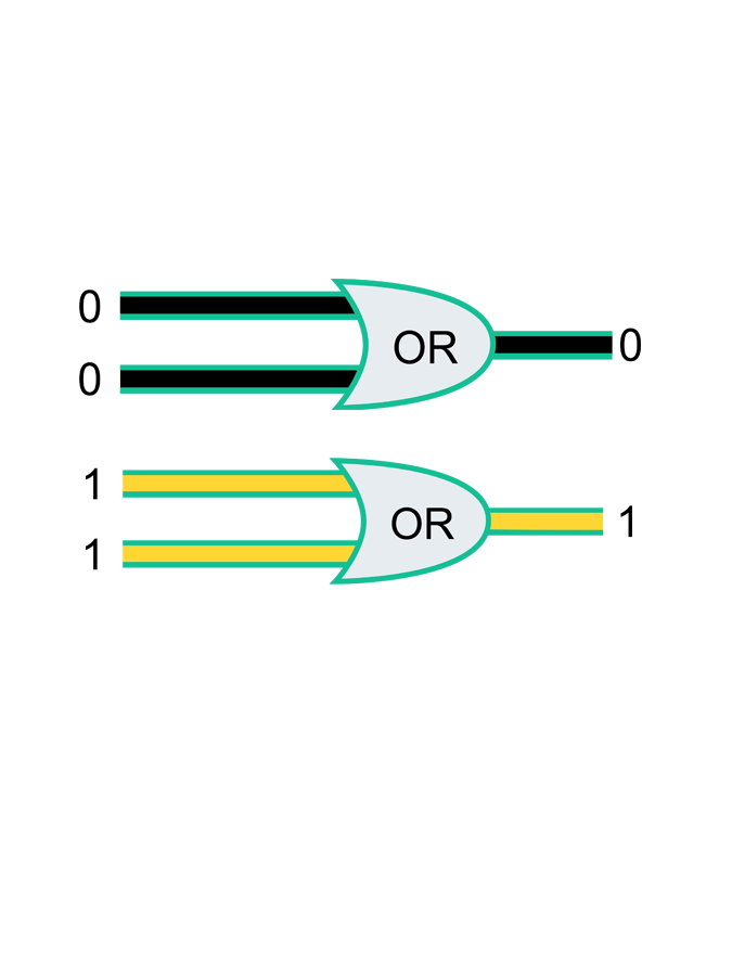
OR GATE
OR gate is a digital logic gate with ‘n’ i/ps and one o/p, that performs a logical conjunction based on the combinations of its inputs.The output of the OR gate is true only when one or more inputs are true. If all the i/ps of the gate are false, then only the output of the OR gate is false.
Click Here
Project 4
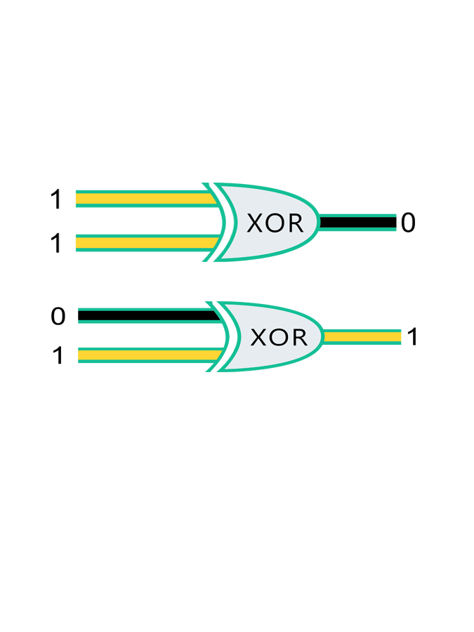
XOR GATE
XOR gate (sometimes EOR, or EXOR and pronounced as Exclusive OR) is a digital logic gate that gives a true (1 or HIGH) output when the number of true inputs is odd. An XOR gate implements an exclusive or; that is, a true output results if one, and only one, of the inputs to the gate is true. If both inputs are false (0/LOW) or both are true, a false output results. XOR represents the inequality function, i.e., the output is true if the inputs are not alike otherwise the output is false. A way to remember XOR is "must have one or the other but not both".
Click Here
Project 5
FLIP-FLOP CIRCUIT
Flip-Flop Circuit is a circuit that has two stable states and can be used to store state information – a bistable multivibrator. The circuit can be made to change state by signals applied to one or more control inputs and will have one or two outputs. It is the basic storage element in sequential logic. Flip-flops and latches are fundamental building blocks of digital electronics systems used in computers, communications, and many other types of systems.
Click Here
Project 6
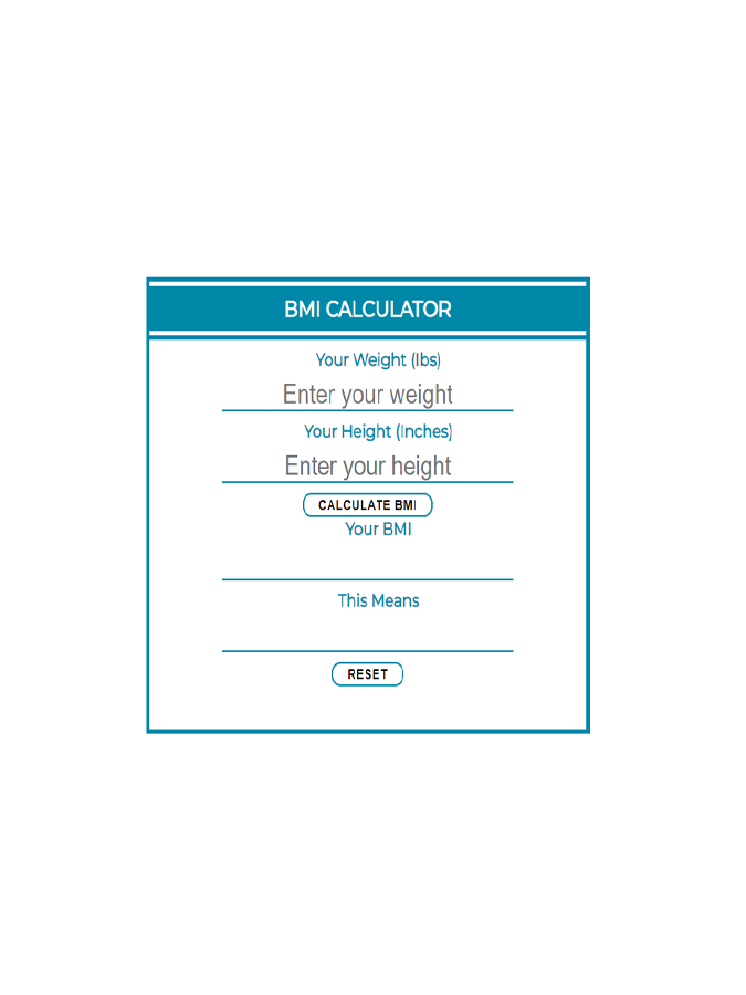
BMI CALCULATOR
BMI Calculator Body mass index (BMI) is a measure of body fat based on height and weight that applies to adult men and women.
Click Here
Project 7
TEXT AS UNICODE, HEX TO BINARY, TEXT AS ASCII
Devan Martinez
Student 2: Interactive Web Page demonstrating conversion from Hex to binary, representing text as ASCII, representing text as UNICODE.
Click Here for Hex to binary
Click Here for ASCII Converter
Click Here for UNICODE Converter